
It all started in Kalamazoo, Michigan.
Fuzz, that is. In the mid-‘60s, Maestro brought us the FZ-1, otherwise known to the masses as “Satisfaction.” Yeah, that sound—it was supposed to be a horn-type sound, or so Keith Richards thought. Fuzz fever swept the world shortly thereafter.
It’s funny that an American invention made its way across the pond in 1965. Just 27 years earlier, the first ever transatlantic flight took place, and the Maestro FZ-1 had to voyage 3,800 miles within a traveler’s luggage just to arrive at the feet of Mr. Richards.
In the years that followed, there was a real Western fuzz corridor formed between the US and UK; Jimi Hendrix brought an English-made Dallas-Arbiter Fuzz Face back to Seattle, and Englishman Vic Flick procured an FZ-1 and had it modded to what became the Tone Bender MKI by Gary Hurst in the back room of Macari’s. For a while, the fuzz flowed like wine along the Germanium Road.

Around this time, the Far East was doing its own thing in the fuzz department, and its insularity worked in quietly subverting the West’s stranglehold on fuzz. The secret weapon: silicon transistors. After Gordon Teal of Texas Instruments invented the first commercialized transistor in 1954, it didn’t take long for Japanese semiconductor company Toshiba to start making its own. Toshiba transistors were manufactured in Tokyo and all bore the prefix “2SC” in compliance with the newly-instituted Japanese Industrial Standard. These transistors began showing up in Shin-Ei’s pedals including the Uni-Vibe, Super Fuzz and Companion. For those of you who care about that sort of thing, the part number was 2SC828.
The fuzz that came from this era was characterized by harsh, biting timbre that immediately made its presence felt. In contrast to the smooth, violin-esque sustain being trotted out by its Western counterparts, the Japanese fuzz boxes wanted to mess your signal up in a bad way. Sustain was often an afterthought, and the fuzz laughed as it tore your guitar sound to pieces. It wasn’t until Pete Townshend’s use of the Univox Super Fuzz that East and West met and shook hands. The Super Fuzz became the stuff of legends, and the Companion was almost forgotten.
Fast forward to 1992, when Wata of Japanese band Boris brought the Companion back into the limelight. Suddenly, used prices shot up, with the dust barely having a chance to be brushed off before the units started flowing out of bargain bins and into the hands of fuzz-crazed players. Today, the sound is recognized as having a completely unique tone, with just one specific buzzsaw sound; piercing, eclectic, and very indicative of Japanese Fuzz. Unfortunately, the older ones are plagued with two problems: They make one sound, despite having a “Fuzz” control that does nearly nothing, and perhaps most egregious, even with the volume all the way up, the unaffected guitar is louder than the fuzz. Today, you will build one, and I have fixed both of these problems by adding a JFET boost (Escobedo Duende) and a Mid Scoop knob that drastically alters the character.
Disclaimer: Neither I, nor Tone Report Weekly bears any responsibility for any kind of personal or property damage that may occur as a result of the instructions provided herein. Legal mumbo-jumbo aside, we ask that readers be familiar with a soldering iron and its accompanying safety procedures before trying anything listed here. Furthermore, if you fire the pedal up and it does not work, it will need troubleshooting. Assuming the components are not damaged, the pedal will work. I built this very unit according to these instructions and it fired up, first shot, so I know the instructions are correct.
Ok, that said, let’s build that circuit board!
Materials
RESISTORS:
- 1x 5.1k
- 1x 10k
- 1x 15k
- 1x 22k
- 1x 47k
- 2x 100k
- 1x 1.2m
- 1x 2.2m
CAPACITORS:
- 2x 1nF/0.001uF
- 1x 2.2nF/0.0022uF
- 1x 3.3nF/0.0033uF
- 3x 47nF/0.047uF
- 2x 100nF/0.1uF
TRANSISTORS:
- 2x 2n2222a (metal can)
- 1x J20
POTENTIOMETERS:
- 1x 5kB (linear)
- 1x 50kB (linear)
- 1x 1mB (linear)
MISCELLANEOUS:
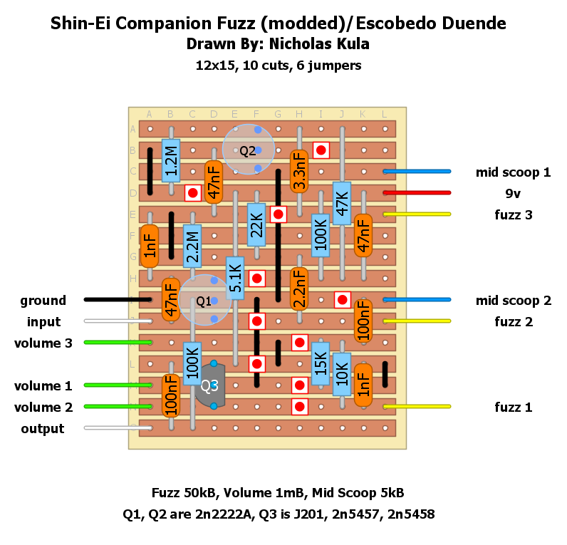
- Stripboard (veroboard) prepared to the specifications of the diagram
- 3x Transistor socket
- Wire
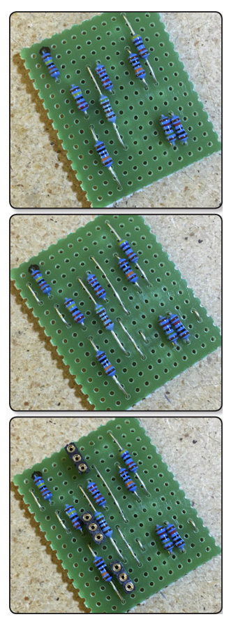
Step 1: Insert the resistors as shown, bend the leads and solder them in. Clip the leads and save them.
Step 2: Use the resistor leads as the jumper wires. Save one more lead.
Step 3: Insert the transistor sockets and solder them in.
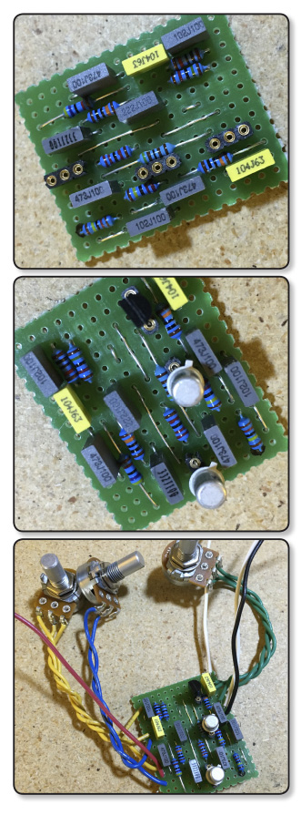
Step 4: Insert the capacitors, bend and clip leads, then solder them in.
Step 5: Cut the transistor leads and insert them into the sockets. Note: the tiny tabs on the transistors should face downwards. If using a different FET than the J201, check its pinout and make sure everything lines up correctly.
Step 6: Attach the wires as labeled, make sure you measure the length of the wires in adherence to your enclosure! Having to re-wire something because of miscalculation is no fun. Attach the wires to the potentiometers.
Now, let’s build that enclosure!
WHAT YOU’LL NEED:
- 1x Enclosure, drilled for three knobs, one LED, one footswitch, two jacks and one power jack
- 2x Mono quarter-inch jacks
- 1x DC power jack
- 1x LED
- 1x LED bezel in complementary size to LED
- 1x 3PDT footswitch
- 3x Knobs of your choosing
- 1x 2.2k resistor
- 1x saved lead from earlier
- Wire
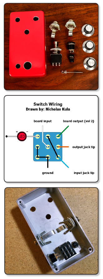
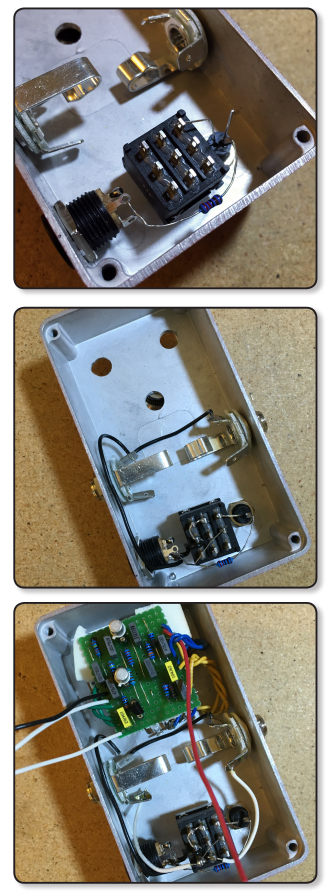
Step 1: Mount all the hardware as shown. I like to mount my jacks in this way to reduce the length of the wires running to the switch.
Step 2: Thread the negative (shorter) leg of the LED into the accompanying spot on the footswitch. If your LED isn’t close enough, use a wire. Attach the 2.2k resistor to the other leg of the LED and thread it into the DC jack, but do not solder it. If you have enough room, thread the resistor leg through both “alike” holes on the DC jack. These are the positive terminals.
Step 3: Make sure the entire circuit is grounded. You’ll start with the three linked lugs on the footswitch, then you will move on to grounding the DC jack, both sleeve lugs of input and output jacks, and you will attach the circuit board ground to one of these, depending on your own hardware layout.
Step 4: Use the spare lead and attach lugs 4 and 9 on the footswitch. Solder only lug 4. Then, mount the circuit board and attach wires to all relevant places (footswitch, DC power, ground). Attach the jacks’ tip lugs to the switch according to the diagram.
Step 5: You’re finished!
Some things to note: With 2n2222As, the collector pin is in electrical contact with the case. This means that if your transistors are too tall and touch the lid of the enclosure, the collectors will be grounded and you won’t hear a thing. You can remedy this by being extra diligent with your pin trimming, or by putting some electrical tape on the lid of the enclosure.
So, what does it sound like?
The JFET boost in place of the volume control really does the trick, as unity gain is now around 8 o’clock, with the potential to drive the front end of your amp. The mid scoop control we added really opens up the range of the pedal, as the original Fuzz control is something of a “flavor selector” but doesn’t appear to do much. The result is all the searing tone of the original Companion with a drastically increased range. Don’t believe me? Here’s Andy playing it through his Deluxe Reverb reissue. Until next time!