The warm sounds of 1960s electronic "combo" organs from makers like Vox, Farfisa, Ace Tone, Yamaha, Elka, and more have been heard in popular music for more than 50 years.
Though the majority of vintage organs that exist today have their share of issues, as some of the first fully electronic instruments ever made, they are also some of the simplest. You tend to find that most suffer from the same types of problems. In fact, probably around two-thirds of the combo organ problems I fix at my repair shop Bell Tone Synth Works fall into a few main categories, and they are things that anyone who knows how to solder could fix at home.
This makes combo organs a great place to start if you’re interested in learning more about the "guts" of electronic instruments or getting into restoring vintage gear. Once you learn how to handle these issues, you’ll be ready for many of the problems that can crop up in a currently working organ and be on your way to being able to restore a non-working organ to its former glory.
Tools And Supplies
Because organs are so simple, you don’t need many fancy tools or supplies to work on them. Here are the basics.
Contact cleaner: Get a product labeled "electrical contact cleaner" or "electronic contact cleaner" that does not contain added lubricant.

DeOxit D100: This "contact conditioner" is expensive and leaves an oily residue, so I use it sparingly, but for those occasions when contact cleaner alone doesn’t quite cut it, it’s a big help. However, this isn’t an essential item.
Soldering Iron: A decent, temperature-controlled soldering station makes a huge difference. You can get pretty good one for as little as $40–$50.
Solder: It is necessary to use lead-based solder when working on vintage electronics. A lead/tin 60/40 blend with a rosin core and a moderate gauge (.062") works well.
Desoldering tool: I use a powered vacuum desoldering station in my workshop, but before I shelled out the cash for that, I was pretty happily using desoldering wick for all my desoldering. "Solder sucker" hand pumps can suck up more solder more quickly, but can be messy.
It might be worth getting both (they’re both inexpensive) and seeing which you prefer. You can also use them in combination. When removing components from vintage organs’ rather crude circuit boards, you can also often simply pull a component out with pliers while heating its solder with your regular soldering iron.
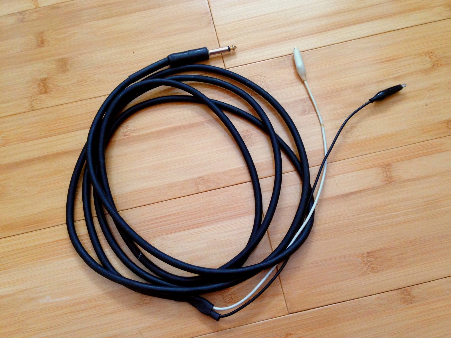
Audio Signal Tracer: When working on organs specifically, I probably use this more than my multimeter and almost never need to use my oscilloscope. You can buy one or make one by taking a ¼" mono cable, cutting one end off, and then soldering one alligator clip to the shield (ground) and one to the "hot" wire.
You can use it to "listen in" on your audio signal path in any piece of electronic gear. But be aware—these signals can be much hotter than line level, so if you’re using a homemade signal tracer with no resistance like this, keep your amp turned down very low. It’s good to have a multimeter too.
Hand tools: Small pliers with wire cutter or, preferably, small pliers and separate diagonal cutting pliers. Flathead and Philips-head screwdrivers, average size (#2).
Schematics: You can most likely find the service manual or schematic for your organ for free online. I suggest trying to follow along with it as much as you can as you work on your organ, even if you don’t yet understand most of it.
Vacuum: Once you open up the top of the organ, you’ll probably find that it’s very dirty inside. Feel free to go ahead and vacuum it out as much as you can with a vacuum cleaner’s brush extension. Your organ can handle it.
Also, don’t forget to make sure the organ is unplugged while you’re working on it!
Dirty Switches
The first problem you’re likely to encounter on a vintage combo organ is dirty rocker switches. Sometimes you’ll hear a ton of crackly, crunchy noise when you change the position of a switch, or sometimes, it’ll be so dirty that it will seem to not work at all—you’ll turn a sound setting on and hear no change.
The solution to this is simple once you take apart the organ to the point that you can access the back or underside of the switches. You’ll see that the back of every rocker switch involves many contact tabs, wires, and springs.
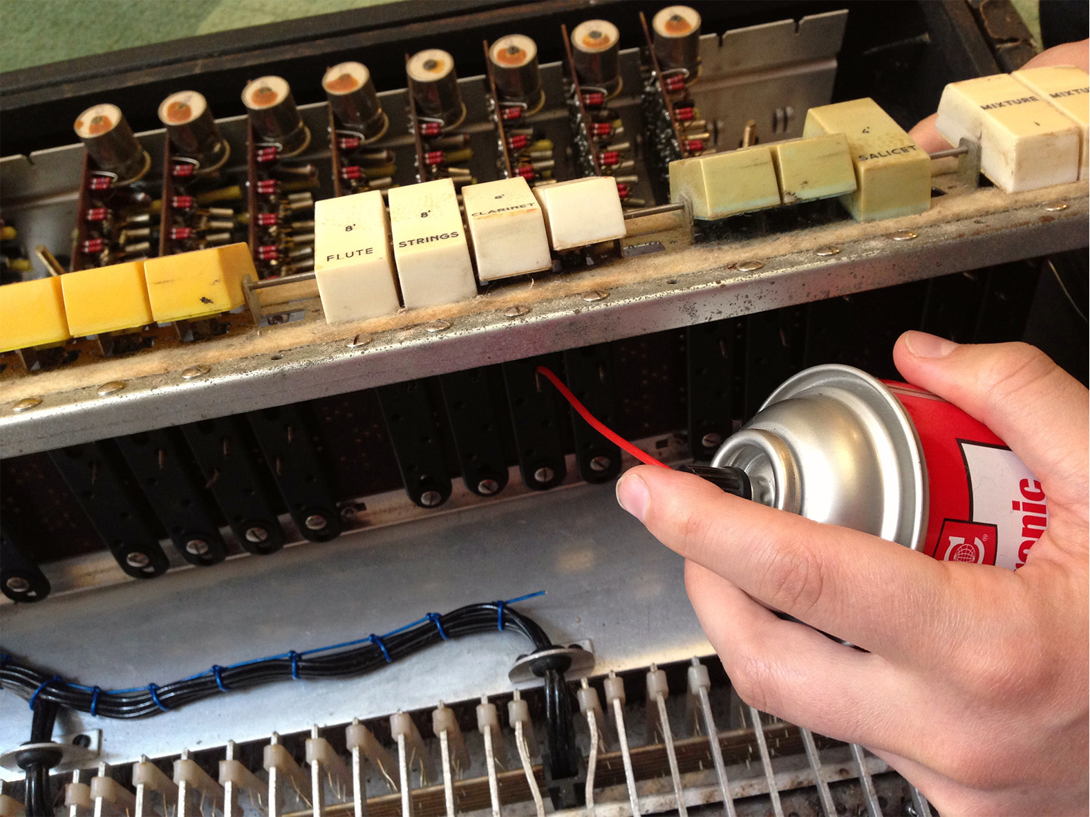
Take your contact cleaner and spray a generous amount into the "guts" of each switch, then switch the rocker switch back and forth 20 to 30 times, turn the organ back on and check the switches for noise, and repeat as needed. If no amount of cleaning stops the crackling, suspect a cold or loose solder joint somewhere. If a switch still seems to do nothing, suspect a more serious circuit-level problem.
Key Contact Problems
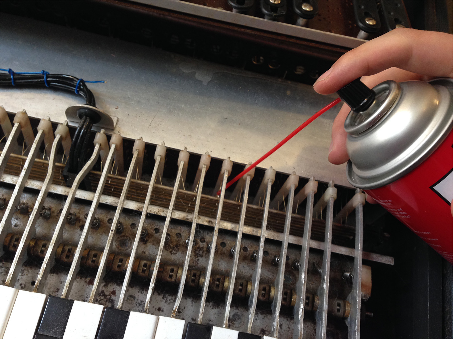
Key contacts are bare metal wires that carry each note signal to horizontal rods acting as passive mixer busses ("buss bars") when you press the key. The mixes on these buss bars then travel to fixed-frequency filters that create the different tone settings.
Plug the 1/4" plug end of your signal tracer into an amp, connect the shield/ground side of your probing end to the metal frame of your organ, and touch a key contact with the tip side. You should be able to hear that note being carried on the key contact.
Dirty key contacts show up as crackling or whooshing noises when you press certain keys. Some keys may work only intermittently, some won’t work at all, or some will work only on certain settings. To address this, you’ll have to continue taking apart your organ until you can access the key contacts, which are underneath or behind the keys.
If possible, you’ll want to clean both the key contacts and the buss bars, but depending on the design of the organ, this can be tricky.
The basic procedure, like with the switches, is to blast the key contact and rod with contact cleaner and work the key up and down many times.
Many organs have many rows of key contacts for different footages, some of which are very difficult to access. In these cases, the best you can do is just keep on shooting contact cleaner in and working the keys, escalating to using Deoxit D100 spray if necessary.
On some organs, you can actually unscrew and carefully slide out the buss bars. If you can, take this opportunity to clean them thoroughly with metal polish. Rubbing them with a soft rubber eraser can also often remove a lot of the tarnish.
Bad Oscillators and Dividers
In a combo organ, each of the 12 notes of the chromatic scale typically has its own small circuit board, often referred to as a "tone generator" and labeled with its note name.
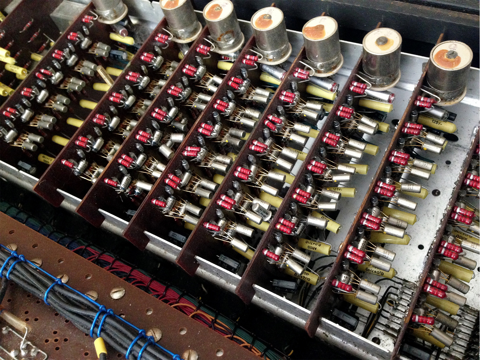
The first circuit on each tone generator board is a simple oscillator with a large inductor coil that you can turn with a screwdriver to tune.
This oscillator produces the highest octave of that note on the keyboard, which is then fed to a series of identical, simple frequency divider circuits. Each of these "octave dividers" divides the frequency of the input signal by two to produce a tone an octave lower.
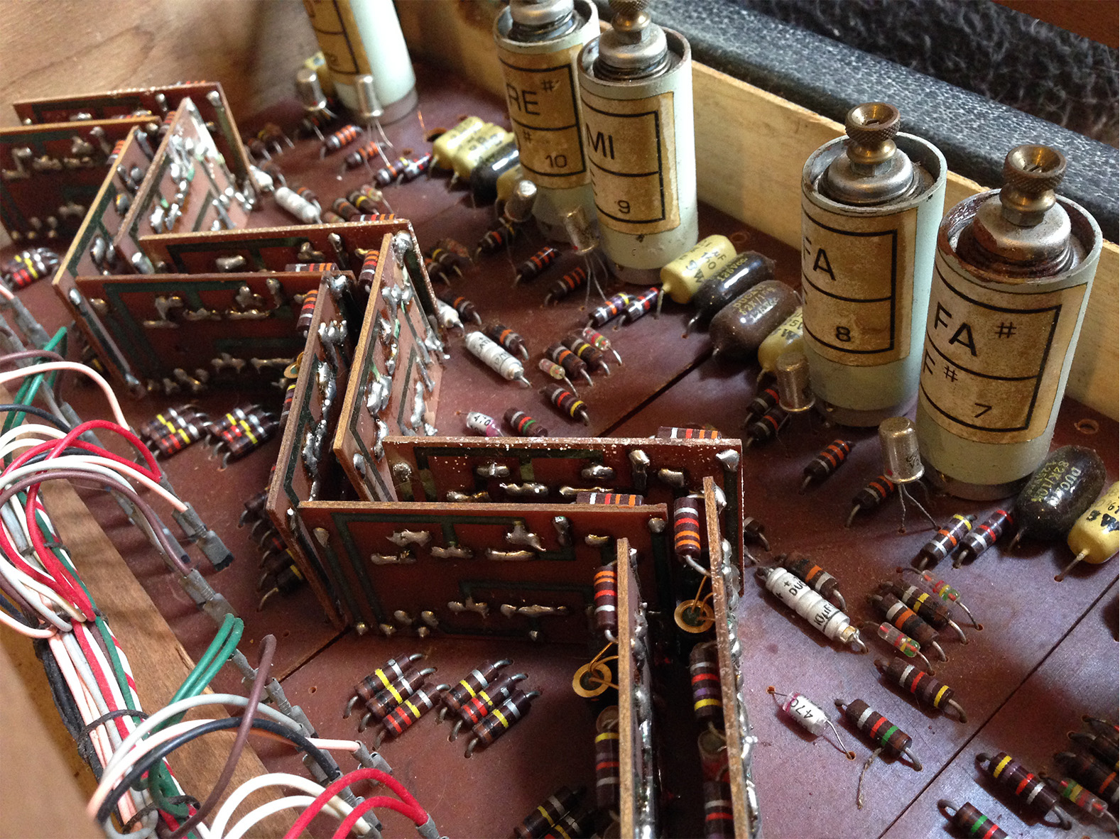
The output of each octave divider is fed to the corresponding key contact and also to the input of the next divider to generate all the octaves of that note needed on the organ.
The repetitive circuitry of the tone generators makes it fairly simple to pinpoint which part of which board is bad if you have notes that aren’t working. If none of a certain note work, you can usually assume that that note’s oscillator is bad. If the top octave or top few octaves of a note work but the lower ones don’t, it’s because you have a bad octave divider.
Since each octave of a note is created directly from the note one octave higher, a single bad octave divider will mean none of the successive lower octaves will work correctly.
Often, the note will pass through a bad octave divider and just not get divided, resulting in keys that produce the wrong octave of their note. Sometimes, lower octaves of a certain note won’t make any sound at all, or their tone will sound buzzy or otherwise mangled. Luckily, there are two main things that cause tone generator circuits to fail the vast majority of the time.
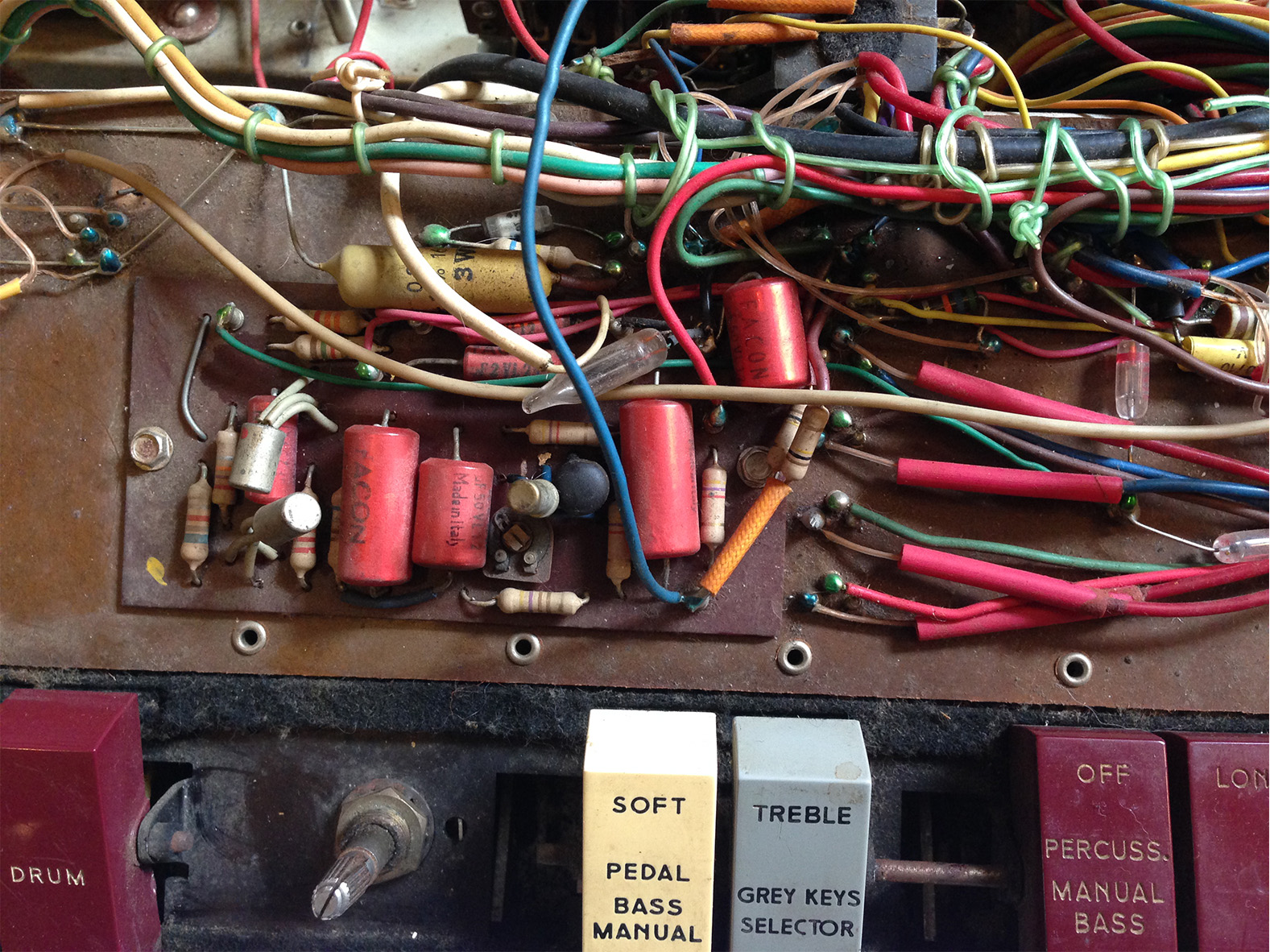
The first thing is the failure of the electrolytic capacitors on the tone generator boards.
A capacitor is a component that temporarily stores electricity (voltage). Electrolytic capacitors are made like batteries, with layers of paper soaked in electrolyte solution. They inevitably fail over the decades as this solution dries up or leaks out. Old electrolytic capacitors typically look like small metal cans and can be either silver or colored.

If a part of the tone generator board (an oscillator or a certain octave divider) is bad, the first thing to do is replace all of the electrolytic capacitors in that circuit section. It’s not worth spending time trying to pinpoint exactly which capacitor is the problem because they only cost a few cents each and it’s better to replace more of them in the long run. In the shop, we actually replace all of the electrolytic capacitors in every organ.
Each capacitor is marked with its capacitance in microfarads (uf or μf) and its voltage rating (V), and you should replace it with one with the same or as close as possible capacitance (up to 20 percent higher or 10 percent lower is fine if you have to get a different value) and the same or higher voltage rating.
Before you remove each old capacitor, take note of which side is labeled with a "+" and "-" sign and put the new one in the same way, as electrolytic capacitors are polarized and can only accept incoming current in one direction.

If replacing the capacitors in the offending circuit doesn’t fix the problem, you’ll progress to replacing transistors.
Although transistors on different organs can look very different from one another, they are easily recognizable. They have three leads (little wire "legs" leading to the board) whereas all the other components you’ll find in an organ circuit just have two. They may look like little metal cans, or they may be black and cylindrical in shape. They could also look like a cylinder cut in half, sometimes with a rounded top.
These bipolar junction transistors can be used for either amplification or switching. On these tone generator boards, they are being used for their switching capabilities, forming audio waveforms as they switch on and off.
Each transistor will have an alphanumeric code on it that identifies what type it is (for example SFT 352, AF-116, or sometimes just a number). Though the obsolete transistors in vintage organs are always going to be out-of-production, you can often find a replacement by searching eBay or other sources that sell salvaged and surplus electronics. If not, other resources on the internet can help you choose a substitute.
Bad capacitors and transistors are also likely causes of problems that you may have in other areas of your organ, like vibrato, tremolo, percussion, and preamp circuits.
An Old Gear Restoration Best Practice: Power Supply Re-cap
There’s one more thing I strongly recommend taking care of if you’re already taking a soldering iron to your vintage organ, and that is replacing the large electrolytic capacitors in the power supply, surrounding the transformer.
These capacitors perform the vital task of making sure the circuits receive a clean and steady DC voltage. If they are old and weak (which they definitely are if they haven’t been replaced yet), it will make your organ noisier and continue to stress the circuits, hastening the failure of more components.
Replacing the power supply capacitors is really a best practice whenever you’re working on old gear. I consider it mandatory whenever I’m working on anything over 25 years old.
Other Weird Things Going on in Organs
While vintage organs are mostly very similar, each one has its own odd design features that can initially be a bit difficult to figure out. Some have tube preamps and reverb tanks. Some have optical (light-controlled) percussion envelope generators.
Some have "slalom" pedals (Farfisa Fast series), filter sweep knee levers, pitch bend ribbon controllers (Yamaha YC series), or ring modulators.
It’s funny to imagine what it was like when they were being churned out by dozens of different companies when the organ world full of cutting-edge innovation and cutthroat competition, with every manufacturer trying to come up with a wacky new feature to set their organs apart.
The more organs you encounter, the more you’ll realize that all these gimmicks are just the same small handful of simple circuit types being combined in different ways.
One last tip—more than a few organs out there were designed to be played through two amps and thus have stereo output jacks that won’t mix down to a mono plug. So if you ever come across an organ in which either the bass section or the rest of the organ’s notes don’t seem to be working, you might just need a stereo-to-mono adapter.
Though the past few years have certainly brought renewed interest in all kinds of DIY pastimes, as well as analog technology, it also seems like the sophisticated and expensive electronics that surround us have made some people more intimidated than ever by the idea of working on electronics themselves.
If you want to learn more about analog electronics and restoring vintage gear, there’s no better way to start than by fixing up something that’s simple, cheap, and busted. Fifty years after the combo organ’s heyday, you won’t have trouble finding an organ that’s desperate for a little attention.